Operating Principle
Acoustic Detection Function: By using the sensor to collect the sound and display signal of pipeline leakage, the collected signal is sent to the host wireless, after the host signal is processed, it is displayed on the host interface in the form of signal columns and values. At the same time, the sound will also be sent to the wireless headset through the host , Through the combination of "listening" and "seeing" two ways to analyze and determine the leaking point.
Gas Detection Function: By injecting hydrogen and nitrogen mixed gas into the pipeline, use a dedicated hydrogen sensor to collect and analyze the leaked hydrogen, detect the leaked hydrogen content, display it on the host interface in the form of signal columns and values, and observe the size changes of the hydrogen content. When the measured position signal column is the highest and the value is the largest, it can be judged that the position is a pipeline leak.
Pipeline Locating function: When the direction of the pipeline is unknown, a sounding device can be installed at the pipeline interface. The device generates a specific sound wave signal mixed with multiple frequencies in the pipeline. The signal is transmitted horizontally along the pipeline in both directions and vertically transmitted to the ground, using the host and the sensor collect this specific sound wave signal on the ground and analyze its strength to accurately locate the orientation and direction of underground metal and non-metal pipelines.
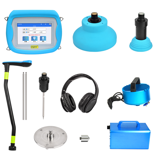
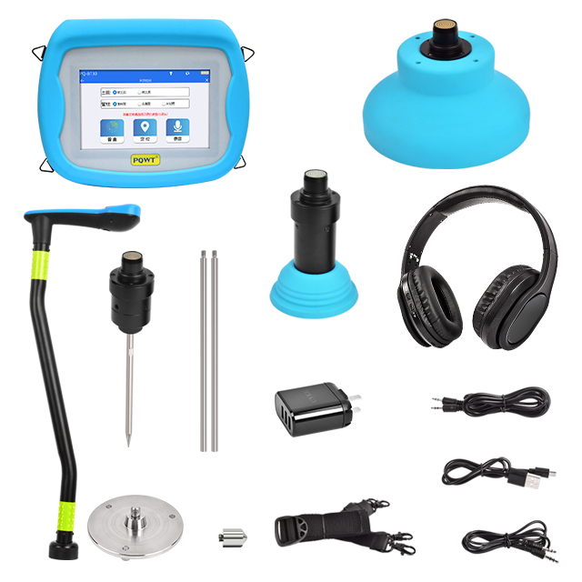
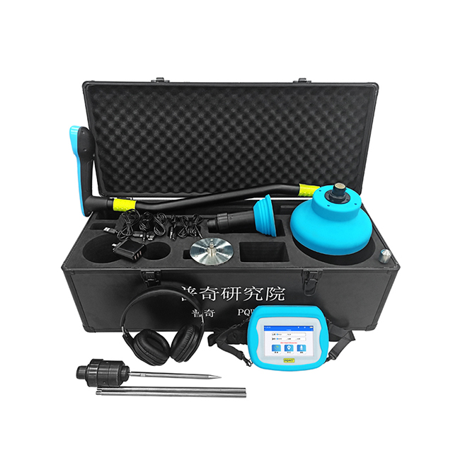
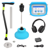
Components
host machine, wireless earphone, wireless controller, three-point base, single-point base, Earphone spare cable, sonde-type sensor, 5V 3A 3-port USB charger, charging cable, host spare cable, host strap,gas sensor, large sensor, sounding vibrator, transmitter

Parameter Configuration
Instrument configuration
standard configuration
Applicable pipeline: External network (tap water, fire fighting, heating)
Frequency
Bluetooth distance
Volume: 10 levels adjustable
Working temperature
Charging time
Standby time
Power
Charger: DC 5V 3A 3-port USB charger
Battery: Rechargeable 18650 parallel lithium battery pack, 3.7V, 6000mAh
Net weight (host machine)
Size
Product model
Gain: 10 levels adjustable
Bluetooth version
Support agreement
Bluetooth frequency
Speaker
Resistance
Speaker frequency
Earphone usage time
Earphone sensitivity
Net weight (Earphone)
Operating voltage
Battery capacity
Transmission frequency
Working hours
Transmitter weight
Sounding vibrator weight
Packing case weight
Packing case size
Main Components Introduction
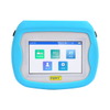
Host machine
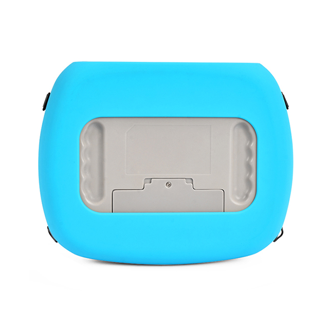
Strap buckle: Used to connect the host machine for easy carrying.
Battery compartments: Long press for 3 seconds to turn on or off.
USB charging port: Use when USB charging or when connected to a computer.
Spare wired earphone jack: For wired earphones.
Microphone: Recording mode, for recording human voice.
Spare wired hole position: For connect the wireless controller to the host machine.
SD card slot: Used for system upgrade, storing recording files, picture files.
Power charging indicator: It is steady green when the machine is turned on, and it goes out when it turned off. It is steady red when charging, and it goes out when it is full.
Reset button: For host system reset, shutdown.
Battery compartments: Battery position
Wireless Controller
USB charging port: Use the DC 5V 3A USB charger to plug in and charge. The green power indicator flashes when charging, and stays on when fully charged.
Spare wired hole position: 2.5mm audio hole position. Emergency use when wireless connection is abnormal.
sensor connection: Connect the sensor. (Refer to the operating instructions for specific methods)
Power charging indicator: Green. It is always on when it is turned on, and flashes when the battery is too low. It will be on for one minute after it is turned off, and then it goes out. The indicator light flashes when charging. Always on after full.
Wireless matching: If the connection waiting time is too long or the connection fails, you can press to refresh the connection and it will automatically search for the host.
Light switch: Press to turn on the light and press again to turn off.
Power switch: Self-locking switch, press to turn on, press again to turn off. (Note: Frequent pressing of the power button will cause the controller to enter the power protection and cannot be turned on. It can be used after activation. To activate, use a charger to connect the charging hole of the controller to power supply.)
Wireless matching indicator: Blue. When the controller is wirelessly matched, the wireless matching indicator flashes, wait for about 1-3 minutes, the controller automatically connects to the host, the blue wireless matching indicator is always on, and the connection is successful.
Gain +: Increase gain, a total of ten adjustable, according to the actual situation.
Gain -: Decrease gain, a total of ten adjustable, according to the actual situation.
Mute: Press to turn on mute, press again to turn off. It can be opened when the controller is picked up during the detection process to prevent excessive noise and ear damage.
Flashlight: for night lighting.
Wireless Earphone
Volume +: Increase the volume, ten levels adjustable.
Volume -: Decrease the volume, ten levels adjustable.
Indicator: Near power switch, blue
Power switch: Long press to turn on or off
Micro USB charging: USB charging port
3.5mm audio jack: for connecting audio cable
Sound device
Transmitter
Switch/power adjustment: Power switch, adjust transmitter output power
Electricity indicator: Steady on in normal state, flashing in under-voltage state.
Running indicator: The running indicator flashes and the instrument is working normally.
Charging hole: For host machine charging
Transmitting output interface: Connect sounding vibrator, signal output interface
25.2 V charger: Transmitter power supply
Sounding vibrator
Sounding vibrator: For specific acoustic signal generation.
Exhaust port: It is used for exhausting and protecting the sound vibrator.
Sound output interface: It is used to connect the interface and output sound signal.
Wire port: Used to connect the transmitter
Adapter
Adapter: for connecting pipes and sound vibrators
Operating Instructions
Host machine
1. Connect the strap to the host.
2. Power on: long press on/off button for 3 seconds. The power indicator is green and the machine is successfully started.
3. Enter the startup interface, as shown in figure 1 below:
(figure 1)
4. Enter the main interface, you can choose the mode as shown in Figure 2 below. There are three modes: acoustic detection, gas detection and pipeline locating , which can be selected according to the actual detection environment:
(figure 2)
5. For leak detection of external network pipelines, click the "Sonic Detection" icon, and the wireless setting interface will appear after clicking. As shown in Figure 3 below:
(figure 3)
Battery display icon
Earphone connection icon. If there is no connection, the state is gray. If the connection is successful, the state is on.
sensor connection icon. If there is no connection, the state is gray. If the connection is successful, the state is on.
Disconnect the existing connection or search surrounding devices, stop searching. Surrounding devices include earphones and stereos.
Earphone and sensors are successfully connected icon.
Return to the previous menu
Exit to the main interface
Device name prompt box. Click the device name in the prompt box to connect.
The status bar prompts. Click Refresh to search for bluetooth devices. Click the device name in the prompt box, the bluetooth device is being connected.
After the earphone and sensor are connected successfully, click to enter the interface for selecting acoustic detection parameters.
As shown in Figure 4 below:
6. Enter the interface for setting acoustic detection parameters and select the corresponding measurement environment parameters, The default parameters are: Soft soil, plastic pipe. According to the red font prompts, combined with the actual measurement environment to select. As shown in Figure 4 below:
Note: The selected measurement parameters cannot be modified after entering the general Detection or positioning interface. Please select them according to the actual situation. In the external detection environment, select an appropriate sensor:
1. The large sensor is suitable for the detection of most outdoor pipelines and other environments, which can effectively reduce noise interference.
2. The sonde-type sensor is suitable for the detection of soft soil, valve wells, fire hydrants and other environments.
(figure 4)
7. According to the detection environment, click "General Detection" to enter the Extranet- General Detection interface, as shown in Figure 5 below:
(figure 5)
Volume icon. The default volume is 6.
Right slider: adjust the volume, slide up to increase the volume, slide down to decrease the volume.
Lower slider: Frequency adjustment, 20HZ-5000HZ, the slider can be adjusted freely. The upper and lower sliders form the frequency range, and the full frequency band is defaulted at boot. It can be fine-tuned according to the actual detection environment and different situations, until the sound heard is clear.
Note: Start testing along the pipeline. In the process of leak detection on the external network, because the pipeline covers a large area, a general survey of the suspicious area can be carried out from the valve well or the fire hydrant first. Compare each point by listening to the sound in the earphone and watching the change of the instrument value on the screen. When the instrument value is high and the sound of suspected water leakage is heard through the earphone, the area can be judged as the suspected water leakage area.
8. Clickto exit the "General Detection" mode, and click "Locating" to enter the extranet -positioning interface according to the detection environment. As shown in Figure 6 below:
(figure 6)
Locating Mode Description:
(1) The extranet -positioning interface can display the collected information of 12 points at the same time, by clicking any position in the column bar of the corresponding point, the signal column can be locked and the signal column can be refreshed, and the corresponding signal value display is displayed above the signal column;
(2) There are 12 bars from left to right, and the detection needs to start from 01;
(3) The columnar bars are divided into thick columnar bars and thin columnar bars. The thick columnar bars are collected stable signals, and the thin columnar bars are environmental instantaneous signals, which will change with the external environment. We mainly observe the thick bar signal;
(4) Click any position in the corresponding columnar bar, a blue columnar bar will appear, and the signal value above the bar will appear in red, and the instrument will start to detect a stable signal;
(5) After the thick columnar bar signal is completely stable and has not fallen, click any position in the columnar bar, and the blue bar will be locked and stationary. At this time, the color of the signal value is black, and the thin columnar bar does not change, indicating the locked state, indicating that the measurement point has been detected. Click again on any position in the columnar bar to refresh the bar to re-detection, and repeat the operation to confirm whether the signal at this point is true and effective.
(6) Use the extranet -positioning mode to collect and compare the signals of relevant points in the suspected water leakage area, each detection point can be directly compared with the signal column, as shown in figure 6 above, detect and compare the signal strength of each point in turn from left to right. When the thick bar of the measured point is the highest and the value is the largest, it can be judged as a suspicious leaking point;
(7) Click to export the pictures of each point detected in positioning mode and save it to the SD card. To view the saved pictures, you need to use USB to connect the computer or take out the SD card and use the card reader to connect the computer to view.
Status bar (operation prompt).
9. For gas detection, click the "Gas Detection" icon on the main interface, and the wireless setting interface (as shown in Figure 3, follow the wireless setting method) will appear to enter the gas detection interface. As shown in Figure 7 below:
(figure 7)
10. Preheat for 3 minutes before using as prompted. Click OK. Enter the gas detection interface, as shown in Figure 8 below:
(figure 8)
The signal column and value display, the larger the value, the higher the gas content.
The value is cleared to 0.
Adjust the spectrum display range.
Spectrum display. The spectrum will change with the value and the size of the signal column.
Note: Hydrogen is needed for detection, and other gas detection is invalid. If there is no hydrogen in the pipeline, it is necessary to fill the pipeline with hydrogen gas, hydrogen will leak out at the leakage of the pipeline, and then use hydrogen detection to complete the pipeline leakage detection.
11. For pipe locating, click the "Pipeline Locating" icon on the main interface, and the wireless setting interface (as shown in figure 3, follow the wireless setting mode) appears to enter the pipe locating interface, as shown in figure 9 below:
(figure 9)
Volume icon. The default volume is 6.
Right slider: adjust the volume, slide up to increase the volume, slide down to reduce the volume, a total of 10 adjustable.
Note: Use the ring detection method to detect along the position where the sound vibrator is installed. Compare each point by listening to the sound in the earphone and watching the data on the screen and the changes in the signal bar, when the value and the signal bar remain high, and the maximum point of sound signal is heard through the earphone, it can be judged that the position is the pipeline position. Mark at this point, continue to measure, finally connect all mark points in turn, and finally get the pipeline direction.
Wireless Controller
1. Connect the sensor to be used at the sensor connection and rotate it to right to mount it. (as shown in the figure). When using a large-size sensor, you can choose to mount the bottom fittings, single-point base and three-point base, both of which can be used on normal road surface, the single-point base is principally applied to flat road surface, In case of rugged road surface, it is recommended to use three-point base, because it can better contact the ground and collect sound signals. Equipped with two different bases, is to adapt to different detection road surface. If it is soil or soft pavement, you can use a sonde-type sensor to insert it into the soft soil. The insertion depth can be determined by selecting the sensor. When hydrogen gas detection is needed, just connect the hydrogen sensor.
2. Press the power switch to start the machine, the blue wireless matching indicator flashes(matching) and is steady on after the matching succeeds. The green power charging indicator is steady on.(Note: Frequent pressing of the power button will cause the controller to enter the power protection and cannot be turned on. It can be used after activation. To activate, use a charger to connect the charging hole of the controller to power supply.)
3. Wireless matching to connect to the host.
Wireless Earphone
1. Power on: long press the power switch button, the blue light flashes quickly, accompanied by a prompt sound, and the power on is successful.
2. Power off: long press the power switch button when the machine is on, the blue light will be off, accompanied by prompt tone, and the machine will be shut down successfully.
3. Volume adjustment: press the "volume +" or "volume -" button to adjust the volume. Press the button to increase or decrease the volume.
4. Bluetooth matching steps: When the bluetooth earphone is matched for the first time, ensure that the distance between the bluetooth earphone and the host within 1M, after the power is turned on by long pressing the "power switch" in the shutdown state, the blue LED light flashes quickly, and the pairing mode is turned on. Enable the bluetooth function of the host or bluetooth device, search for the bluetooth headset device, and select the BT Headset, no matching password is required (some function machines require matching password, please enter 0000 for password connection), If the pairing fails or is invalid, repeat the preceding steps. If the blue LED is on, the pairing is successful.
5. Power off: when the battery voltage is lower than 3.0V, the earphone will automatically shut down.
6. Charging indicator: The blue light is steady on during charging and off when fully charged. The earphone shuts off automatically when charging, If it is turned on without connection or pairing, the earphone will automatically turn off after 5 minutes.
7.
Sound Device
1. Find a pipe connection exposed on the ground in the area to be tested; (as shown in the figure below)
2. Confirm the emptying water and pipeline patency; (The pipe valve needs to be opened, as shown below)
3. Connect the sounding vibrator to the pipe with a suitable adapter. (As shown below)
4. Connect the sounding vibrator to the transmitter, turn the switch and power adjustment knob clockwise, turn on the power on the transmitter, and adjust the pointer on the switch and power adjustment knob to 90°. (As shown below)
Pipeline locating measurement method 1: Ring Detection Method
Take the sound vibrator as the center of the circle and form a circle with a radius of 2 meters. Detect on this circle, mark the highest value point of the signal, and then continuously increase the radius length. Each time the radius length is increased, a measurement is performed on this radius parameter. Finally, mark the maximum value of all signals and connect them into a line, which is the position of the pipe. As shown below:
Pipeline locating measurement method 2: Arc Cutting Method
On the basis of ring detection, the highest value of the signal detected in the ring is connected with the sounding vibrator to form a straight line, taking the sounding vibrator as the circle point, cut the straight line left and right in an arc-shaped way. Each time of cutting, mark the highest value point of the signal, and finally connect all the highest value mark points of the signal into a line, which is the position of the pipeline. (This method is a brief version of the ring measurement method, which can effectively improve the measurement efficiency). As shown in figure below:
Note: the above methods should be combined with the sound device.
Other Functions
1. In the extranet mode, "Recording" is mainly used to collect the sound at the leak point for archiving as leak detection data, as shown in Figure 10 below:
(figure 10)
Click to turn on/off the microphone, and the operator’s voice can be recorded, which is convenient for distinguishing recording locations and making records.
Click to start recording, click again to stop.
Use USB cable to connect to computer, click to connect to computer.
Delete the recording file.
Refresh the file list after recording.
List of recording files.
Operation instructions are displayed in the status bar.
2. Click the "Setting" icon on the main interface to enter the setting interface, where you can set the brightness and language of the instrument. As shown in Figure 11 below:
(figure 11)
3. Click the "About" icon on the main interface to enter the About interface to view various information about the host. If you need after-sales service, you can check the after-sales telephone number and address on this page. As shown in Figure 12 below:
(figure 12)
After-Sales Service
1. Free maintenance
1. The host and wireless controller are guaranteed for two years, the sound device and sensor for one year, the earphone and charger for one month, the battery and other accessories are not covered by the warranty.
2. During the warranty period, if the product function is abnormal caused by non-human factors, you can enjoy free maintenance service.
2. Charged maintenance service
The chargeable maintenance service clause applies to any of the following situations, and is charged according to the actual maintenance cost:
1. Products without valid shopping vouchers; products purchased through unauthorized channels;
2. Product failure or damage caused by improper use or maintenance;
3. Product failure or damage caused by self-disassembly of equipment;
4. Product failure or damage caused by force majeure.
3. After-sales service process
1. Customer contacts the relevant sales staff to confirm the problem.
2. If the machine needs to be returned for repair, the customer shall bear the delivery cost. When sending the machine back to our company, please specify: purchase time, failure status, return address, contact name, contact number and contact sales staff, and send back the warranty card together.
 English
 العربية
 Français
 Español
 Bahasa indonesia
 Türk dili
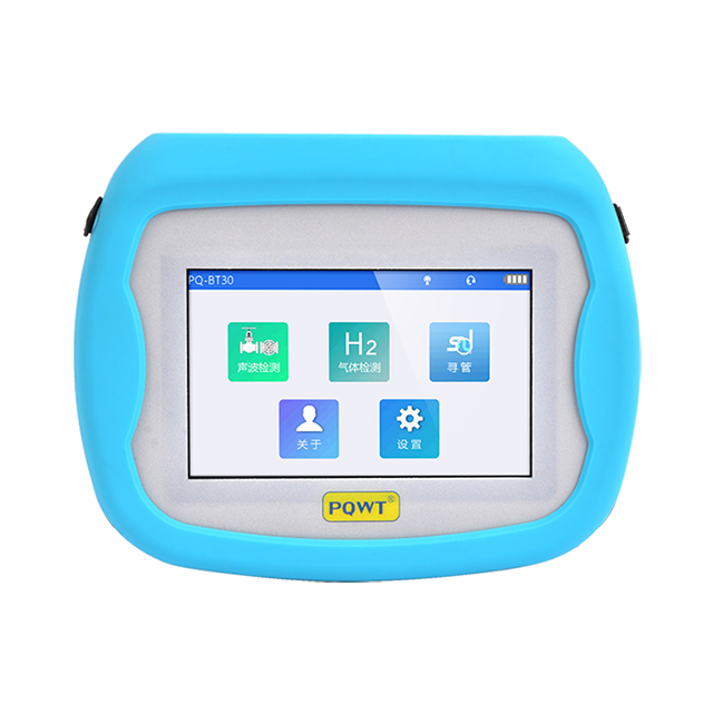


 Volume icon. The default volume is 6.